#Minitel 1B expansion board
This page is made of excerpts from a much more detailed essay I wrote in 2016. You can download it here (.pdf 18 MB), although it’s written in French.
Keywords
FPGA, CPLD, Verilog, JTAG, SVF, Boundary-Scan Testing, microcontroller, assembly, EEPROM, SRAM, memory, in-system programming, voltage level shifting, SPI, bus, controller, peripherals, interrupt, address decoder, registers, SD card, light pen, video sync, audio, DAC
Abstract
The Minitel is a computer modem and terminal set provided by the state to French individuals from 1980 to 2012. The architecture of some models serves as the base for a microcomputer and was designed with the insertion of a daughterboard in mind, in order to enhance the capabilities of the device. To my knowledge, no product benefitting from it was ever released at the time.
This project involves the design and manufacturing of such a daughterboard, the main functions of which are memory expansion and support for various peripherals including a light pen (a kind of pointing device).
To this end, I analyzed the circuit board of a Télic-Alcatel Minitel 1B and drew its electrical schematics, and then designed a compatible daughterboard fulfilling a set of criteria.
Introduction
I got the idea for such a project in late 2014 when, out of curiosity, I took apart a Télic-Alcatel Minitel 1B to study its inner workings. I noticed the designers had provided the device with an expansion connector, the purpose of which was obviously to allow a daughterboard to be inserted and enhance the device’s features. The thought of making such a daughterboard then naturally occured to me with the intent of transforming the original Minitel—a mere terminal with fixed functionality, offering no programming option whatsoever—into a full-fledged programmable microcomputer in glorious 70s/80s style.
A quick Internet search shows that some people have made such a transformation, but through different means: the power and CRT controller board of the Minitel is preserved, while the original motherboard is tossed away and replaced by a modern small single-board computer such as the Raspberry Pi, with an interface board to link the computer to the CRT controller board. Although this is without doubt the quickest, simplest and by far cheapest way to go, this seemed rather uninteresting to me from an electronic engineering perspective and from a functional one (why restrict a modern computer with a black and white CRT screen and a horrendous keyboard?), and most of all it wouldn’t have respected my wish to preserve and use the whole original circuitry. Thus I set out to make a daughterboard which would enhance the motherboard’s capabilities, without replacing it.
Summary of work carried out
Electronic circuits
- Reverse engineering of the complete electrical schematics of a Télic-Alcatel Minitel 1B motherboard
- Understanding of the operation of a light pen and design of a circuit which allows to visualize on a TV the signal it emits
- Design of an expansion board for the Minitel
- Main features of the expansion board: ROM and RAM enabling storage and execution of programs, SD card reader, memory bank switching controller, peripheral controller including light pen, interrupt controller, audio output to speaker or headphones and to phone line
- Choosing of electronic components and drawing of the electrical schematics
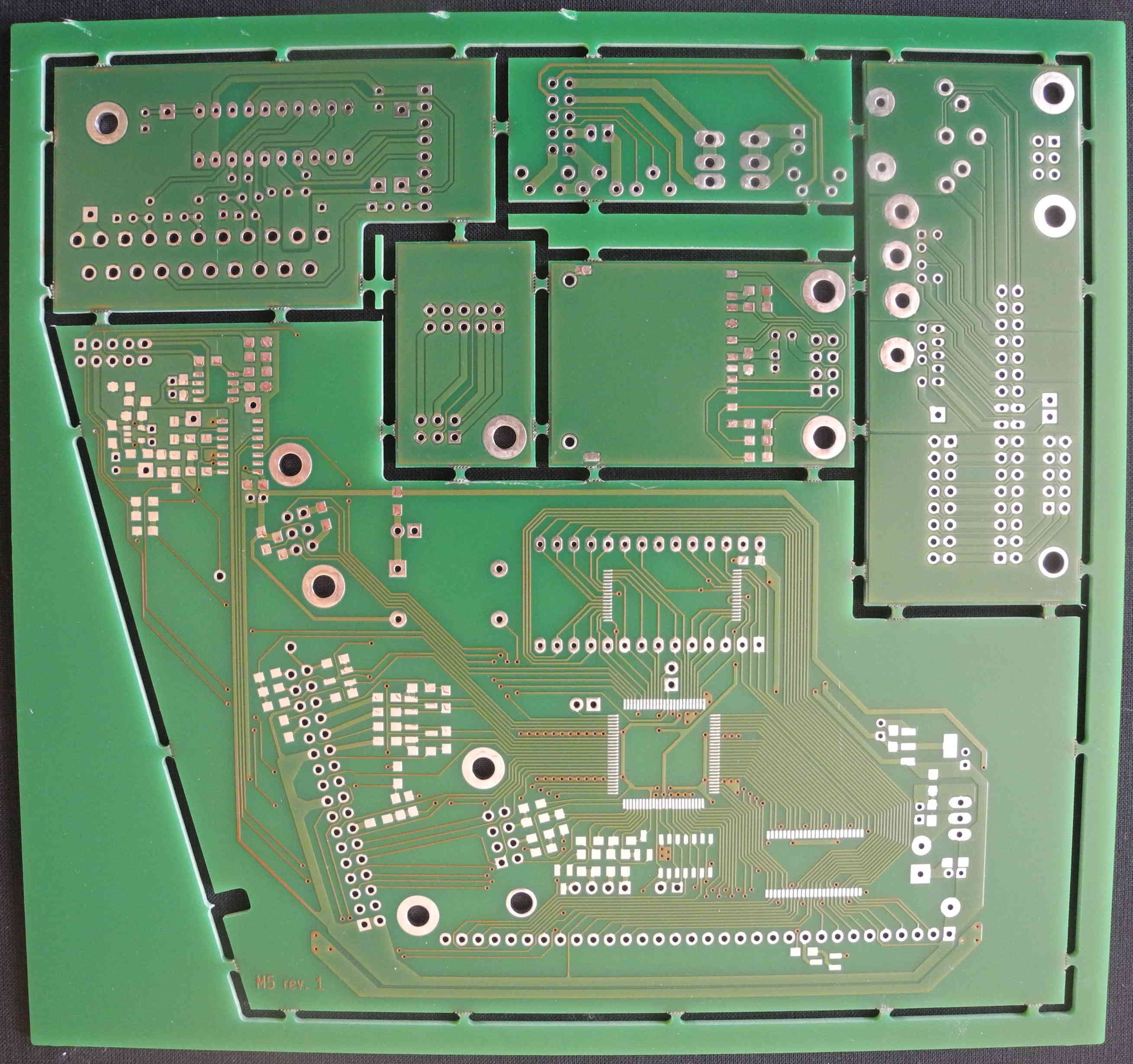
- PCB design using CAD software, layout of the various boards on a PCB panel
- PCB panel manufactured by a factory
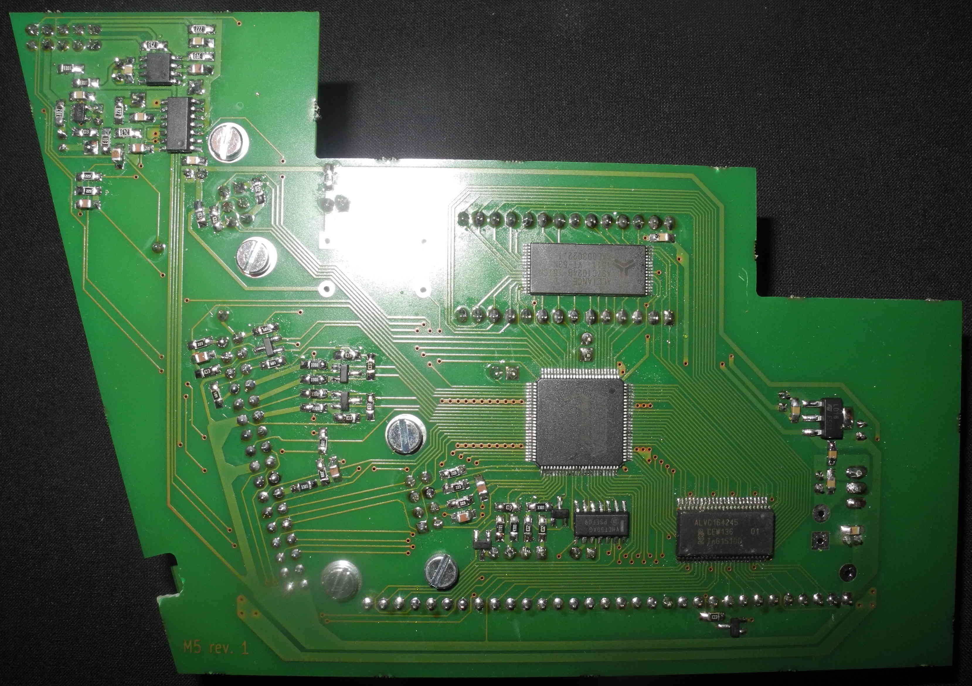
- Component soldering and assembly of the boards
Programmable logic modules coded in Verilog
- Clock divider
- Power-on reset generator
- Memory-mapped I/O and registers
- Address decoder and bank switching controller
- SPI bus master
- Sync separator using a four-state Moore machine
- Light pen controller, whose purpose is to compute and register the light pen coordinates on the screen
- Dual PS/2 port accessed by bit-banging
- Interrupt controller, signalling, among other things, the beginning of a new video frame (vertical sync), the completion of a byte transfer on the SPI bus, the depressing of the light pen switch…
- Ability to use the Minitel for its original purpose, by pressing a switch at startup
Programs for the modified Minitel
- SD card program loader, with minimal support for FAT32
- ROM dump program: reads the contents of the microcontroller internal ROM which holds the Minitel original program
- Rough drawing software using the light pen
- Basic synthesizer allowing to play music using the keyboard and the light pen
- SPI terminal allowing to manually send data on the SPI bus and see the received data
Utility program for PC
- SVF file generator used for the in-system programming of the expansion board EEPROM
Architecture of the Minitel
The Minitel is a terminal equipped with a modem. In a nutshell, it sends to a server the user’s keystrokes and displays the data received from the server. Some typical features of computer terminals such as underlining or cursor positioning are supported.
A glance at the Minitel hardware architecture shows that the terminal functionality is entirely handled in software by a microcontroller. One can also quickly spot a 32-pin header which mainly gives access to the microcontroller address and data bus. It is thus relatively easy to connect a memory chip through this connector and have the microcontroller run a program other than the original one.
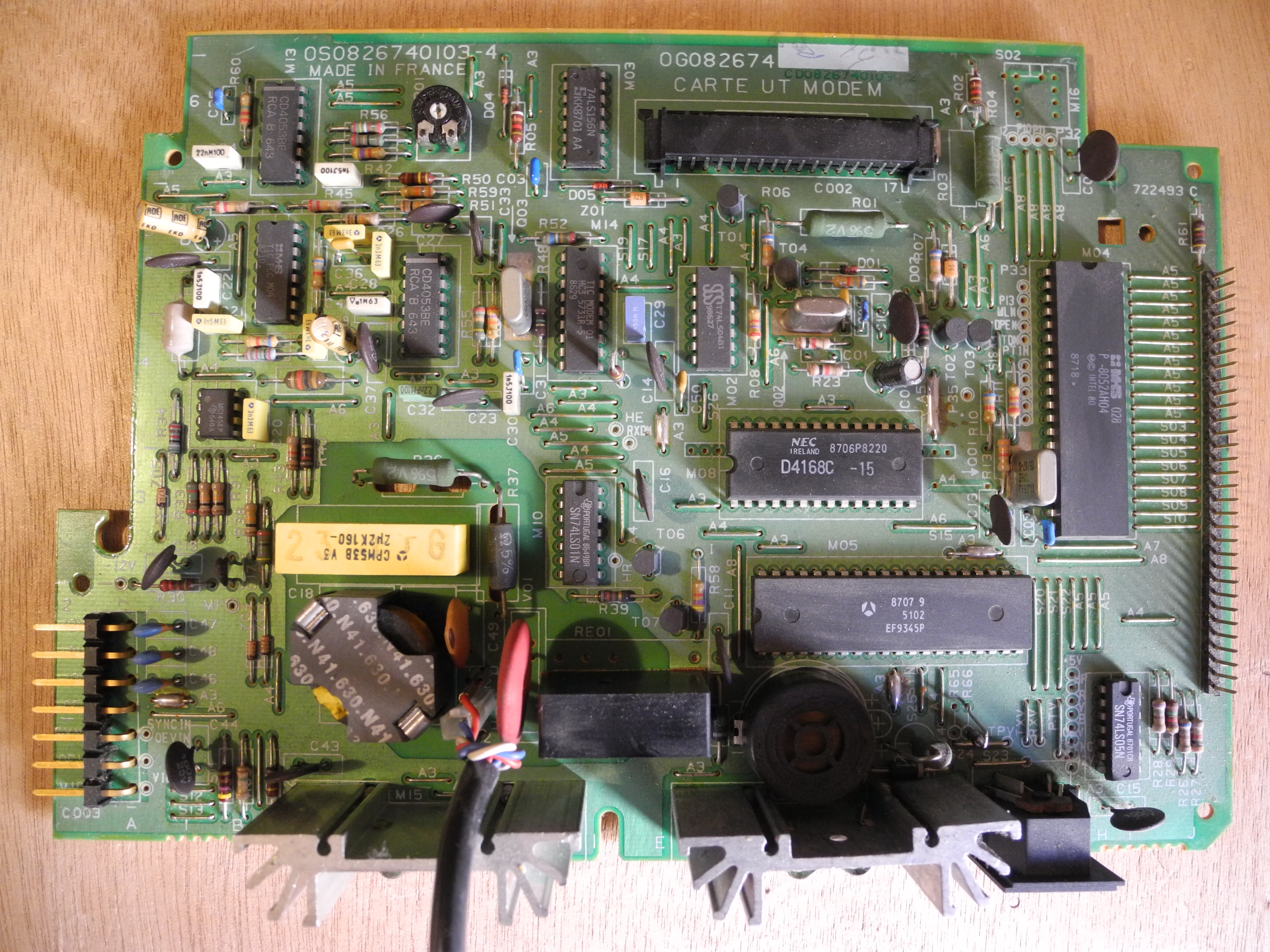
Let me briefly describe the general architecture of the Télic-Alcatel Minitel 1B and its main components.
Before I start, I should point out there are several minor hardware variations of the Télic-Alcatel Minitel 1B. For example, mine is equipped with an 8052 microcontroller with internal ROM, while others have an 8032 (fully compatible with the 8052 but lacking an internal ROM) and a daughterboard which holds a ROM chip and is plugged onto the pin header. Everything that follows relates to the model I own; some statements might not be applicable to other models.
The hardware can be broken down into six main parts: the case, the keyboard, the black and white CRT screen, a small circuit board bearing the text FILTRE SECTEUR (mains filter), a large board titled CARTE ALIM VIDEO (power supply and video board), and a large board titled CARTE UT MODEM (processing unit and modem board). For convenience, I will call the latter motherboard.
I will then talk only about the motherboard for it is the only piece of circuitry which is of interest for this project, and it is the only one which has to be interfaced with the expansion board.
The figure below shows the hardware architecture of the Minitel in a simplified fashion.
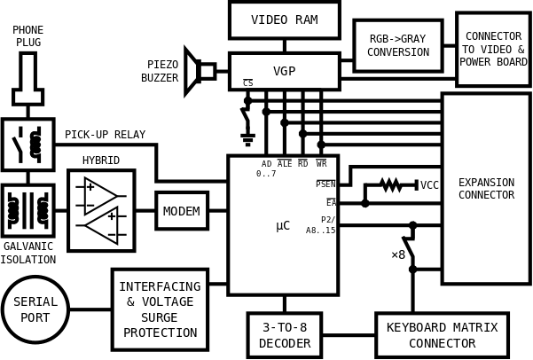
The two fundamental components of the motherboard and the most interesting for this project are the microcontroller and the graphics processor.
- 8052
- Famous Intel microcontroller from the MCS-51 family, still used today in industrial context. It has an 8-kilobyte ROM and a 256-byte RAM. It has the particularity of having its address and data bus directly accessible on its pins, just like a conventional microprocessor, which allows for the execution of programs stored in external memory.
- EF9345
- Display processor made by Thomson, featured in some French microcomputers such as the Philips VG5000µ or the Matra Alice 32. It requires a dedicated external RAM. It generates a TTL digital video signal with 3- or 4-bit color, in a TV-compatible standard (vertical resolution, sync timing…). It can display alphanumeric characters and semigraphics. For convenience, I will call it VGP (Video Graphics Processor), a designation officially used by the French PTT (the former administration of postal services and telecommunications) in their Spécifications Techniques d’Utilisation du Minitel 1B.
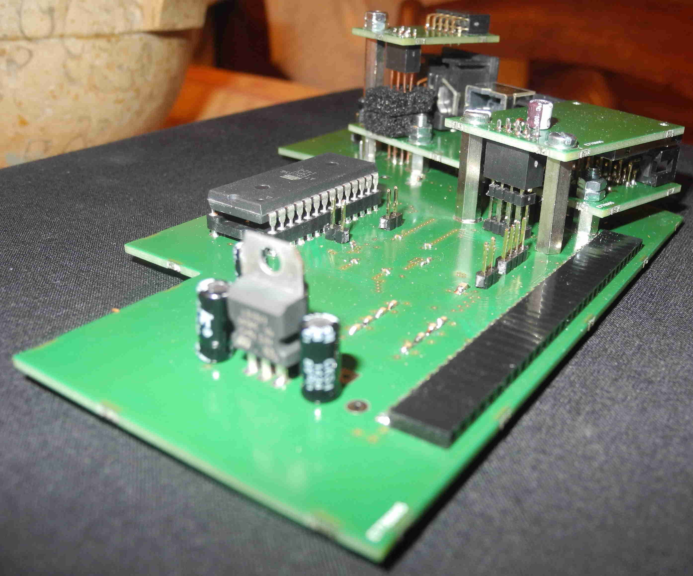
Expansion board technical specification
| Programmable logic | CPLD/FPGA Altera MAX V EPM240ZT100 |
| Memory | EEPROM 64 Ko RAM 128 Ko |
| Storage | SD card |
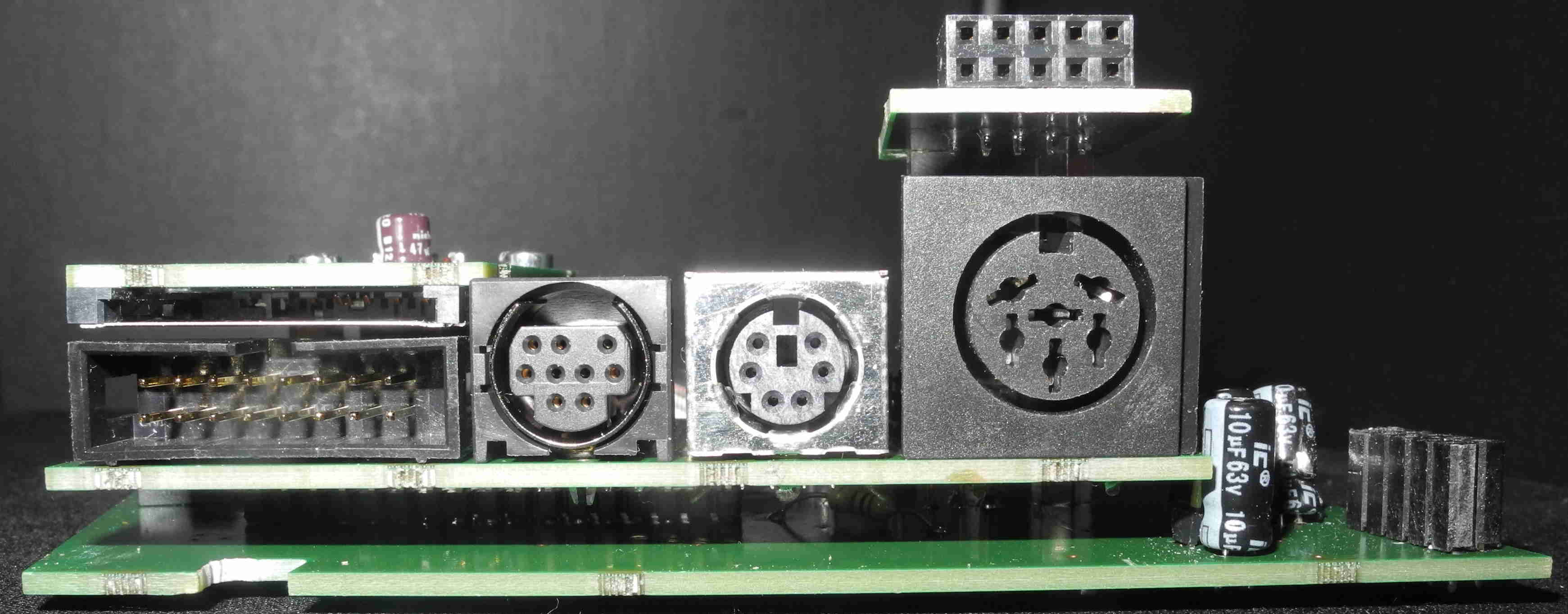
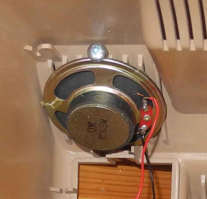
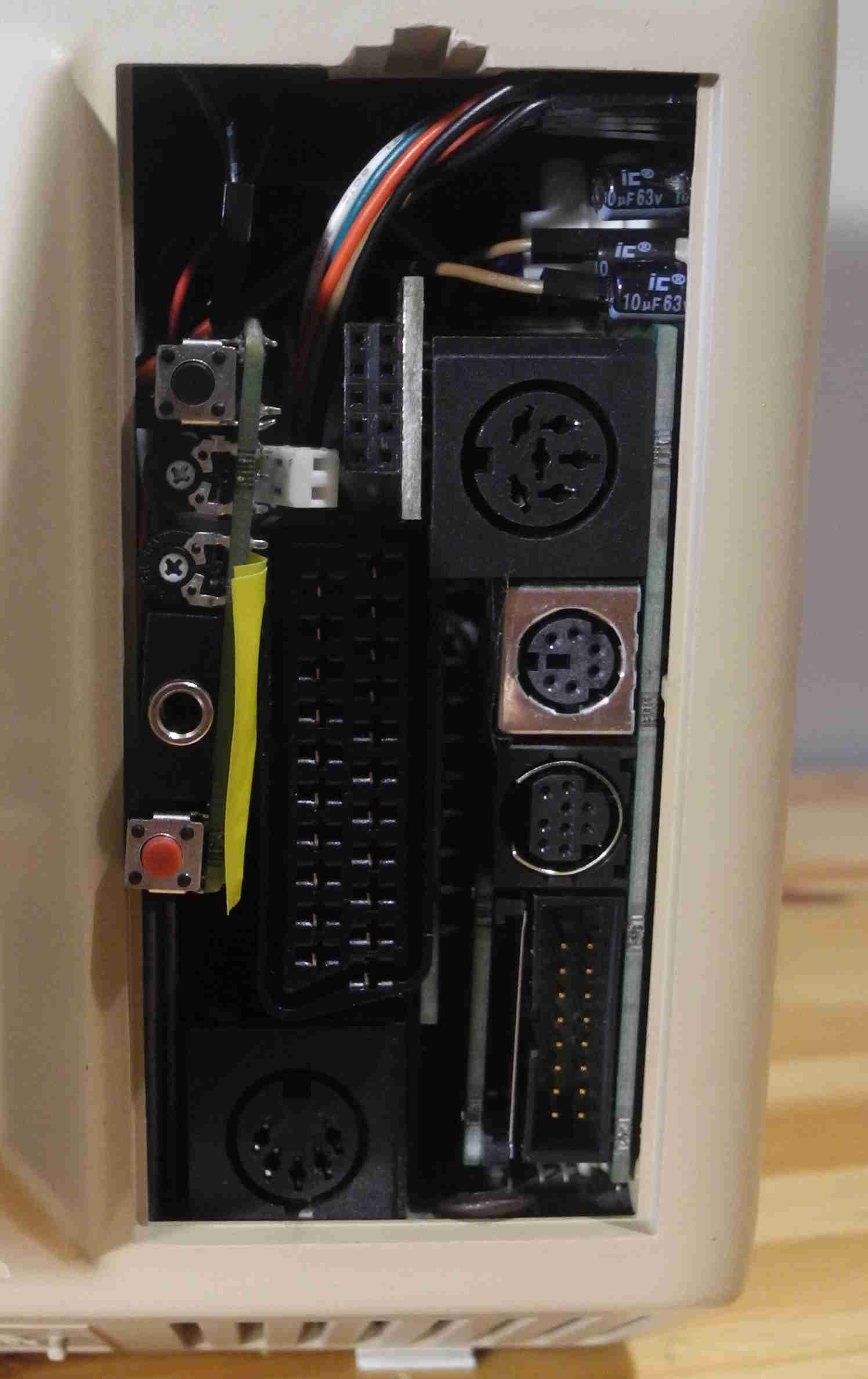
| Audio & Video | 8-bit mono sound output to internal speaker or headphone jack 8-bit mono sound output to phone line audio and RGB video output to SCART socket |
| Peripherals | Dual PS/2 port light pen |
| Expansion | SPI bus connector with four selection lines, reset line and interrupt line input connector for audio and video inlay |
| Switches | reset switch interrupt switch |
Alterations to the motherboard
Some alterations have to be made to the motherboard: take off a few jumpers, add some pins in order to access signals which are not available on the expansion connector (e.g. the microcontroller RESET and INT0 lines), and some other minor modifications.
Motherboard schematics
Click here (.pdf 13 Mo) to download the electrical schematics of the motherboard. I can’t in all honesty guarantee it doesn’t have any mistakes, especially on pages 6-7. I apologize for the terrible quality of the schematics, which are hand-drawn. I was lacking time and doing the schematics over on a PC wasn’t a priority.
Expansion board schematics
Click here (.pdf 600 Ko) to download the electrical schematics of the expansion board.
Pictures


This program allows the user to make a rough drawing on the screen using the light pen. The roughness of the drawing isn’t due to a lack of precision from the light pen, but to the fact that, in order to make the coding of the software easier, I restricted the granularity of the drawing to the size of character cells. It is possible to achieve a finer drawing by using the VGP semigraphics or custom characters.
Light pen demo video
Related project
I can’t possibly end this article without pointing out the amazing work Jean-François Del Nero, aka HxC2001, did on the Minitel 2. Be sure to check out his impressive 2D and 3D demo, it’s really worth seeing!